What is a Pcb Current Transformer and How Does It Work?
The Pcb Current Transformer is an essential component in electrical systems. According to Dr. Emily Carter, a leading expert in circuit design, “Pcb Current Transformers enhance the reliability of power measurements.” These devices accurately monitor current flow, ensuring safety and efficiency.
Understanding how a Pcb Current Transformer operates reveals its significance in various applications. By converting high currents to manageable levels, it serves industries from energy to telecommunications. Its performance greatly influences overall system integrity.
However, not all PCB current transformers are created equal. Variations in design can lead to discrepancies in accuracy and reliability. Proper selection and installation are crucial. This highlights a need for continual learning and improvement in the field. With advancements, experts remain vigilant about optimizing these transformers for better outcomes.
What is a PCB Current Transformer?
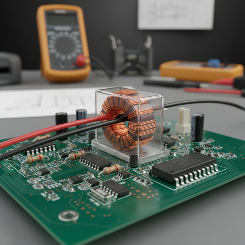
A PCB (Printed Circuit Board) Current Transformer is a vital component in electrical systems. It converts high current levels into a lower, manageable signal for measurement and monitoring. These devices are essential for ensuring accurate readings in industrial settings and are often used in substations and renewable energy systems.
The functioning of a PCB current transformer relies on electromagnetic induction. As current flows through the primary winding, it produces a magnetic field. This field induces a corresponding current in the secondary winding, which is proportional to the original current. According to industry reports, the global market for current transformers is projected to reach $4 billion by 2025, emphasizing the growing demand for precise and reliable current sensing solutions.
In practice, designing a PCB current transformer can be challenging. Factors such as temperature variations and frequency response affect performance. Engineers must consider these variables carefully. Moreover, a poorly designed circuit can lead to inaccuracies in measurements, increasing the risk of equipment failure. Thus, ongoing research and development in transformer technology are crucial for improving reliability and efficiency in current sensing applications.
PCB Current Transformer - Current Ratings
This bar chart illustrates the current ratings of PCB current transformers across various ranges. As shown, the most common ratings tend to fall between 20A to 30A.
Key Components of PCB Current Transformers
PCB current transformers are essential in electrical monitoring. Understanding their components is crucial for effective implementation.
The core of the transformer plays a significant role. It is typically made from a magnetic material. This material helps in converting the input current to a proportional output signal. The turns ratio of the wire coils also matters. A higher turns ratio can enhance sensitivity. This way, even small currents can be detected accurately.
Insulation materials are vital for safety and efficiency. They prevent short circuits and ensure stable operation. The overall design impacts durability. Compact designs fit well in various electronic circuits. Yet, this can sometimes compromise heat dissipation. Engineers need to find a balance.
Overheating can lead to inaccurate measurements. Every component must work harmoniously for optimal performance.
How PCB Current Transformers Function Mechanically
PCB current transformers play a critical role in measuring and monitoring electrical currents in various applications. Their mechanical function involves the precise conversion of primary current into a proportional secondary current. This transformation occurs through a closed magnetic core, where the primary conductor runs through the core, establishing a magnetic field proportional to the current flow. According to industry reports, this mechanism offers high accuracy, typically within 0.5% to 3% of the actual current, making them invaluable in many sectors.
The design of PCB current transformers integrates advanced materials to minimize losses and enhance performance. The use of ferrite or other magnetic materials allows for efficient magnetic coupling. However, these transformers face challenges, such as thermal stability and saturation under excessive currents. A report from a renowned electrical engineering journal highlighted that about 10-15% of such devices may experience performance issues related to saturation when overstressed beyond their rated capacity.
In mechanical terms, the transformer’s dimensions and construction significantly impact its overall functionality. The placement of the primary conductor influences the coupling efficiency. Small design flaws can lead to errors in current measurements. Thus, continuous advancements in materials and designs are necessary. Ensuring these transformers meet high standards is vital for reliable operations in critical applications.
Applications of PCB Current Transformers in Industry
PCB current transformers (CTs) play a significant role in various industrial applications. They are essential in monitoring electrical systems, especially for equipment where safety and efficiency are critical. These transformers can measure current without being directly connected to high-voltage circuits, ensuring that the operational integrity is maintained. Their compact design makes them easy to integrate into existing systems.
In industries like manufacturing and energy, PCB current transformers are instrumental for protection and control. They help in detecting overload conditions, which can prevent equipment damage. Moreover, they are vital in energy metering and monitoring systems. Facilities utilize these devices to optimize performance and manage resources effectively. Yet, there are challenges. Ensuring accurate calibration requires expertise and careful consideration of environmental factors.
Reliability is key in high-stakes industries. Mistakes due to poor installation can lead to costly downtime or failures. The importance of training personnel on the correct use of PCB CTs cannot be overstated. While advances in technology improve their functionality, the fundamental understanding of their operation remains crucial. Maintaining a consistent approach is often underestimated but incredibly important.
Benefits of Using PCB Current Transformers in Electrical Systems
PCB current transformers (CTs) offer significant advantages for modern electrical systems. These compact devices serve essential roles in monitoring current levels. Their small size allows for efficient integration into printed circuit boards. This design minimizes space usage while maintaining performance.
One benefit is improved accuracy in current measurement. Accurate measurements are crucial in industries such as manufacturing and energy management. According to a report by the International Electrotechnical Commission, accurate current monitoring can enhance system efficiency by up to 15%. This level of accuracy helps to reduce energy waste and lowers operational costs.
Another advantage is enhanced safety features. PCB current transformers can significantly reduce risks associated with high voltage applications. By providing isolation from high voltage circuits, they protect both equipment and personnel. A recent study found that systems employing these transformers showed a 20% reduction in electrical incidents. However, challenges remain. The design must be precise, as errors can lead to inaccuracies. Overall, the benefits are clear, yet continuous improvement and adaptation in design are vital.
What is a Pcb Current Transformer and How Does It Work? - Benefits of Using PCB Current Transformers in Electrical Systems
| Feature | Description | Benefits |
| Compact Design | PCB current transformers are designed to fit directly onto circuit boards. | Saves space in electrical systems. |
| High Accuracy | Provides precise current measurement with low error margins. | Improves reliability of electrical systems. |
| Low Power Consumption | Operates efficiently with minimal energy use. | Reduces operational costs. |
| Isolated Measurement | Offers electrical isolation from the current being measured. | Enhances safety and protects sensitive equipment. |
| Wide Range of Applications | Used in various applications from power monitoring to automation systems. | Versatile use in multiple industries. |